How to Build Topography From Autocad Drawing in Revit
14 Tips to Master Topography and Landscape in Revit
Let's be clear: Revit's default landscape and site tools are not very good.
Landscape architects and users modelling complex sites often get frustrated by what is offered by Autodesk.
The good news is that the community took things into their own hands, found great workflows, and build amazing plugins to solve issues and pain points with the landscaping features.
This guide wouldn't be possible without Lauren Schmidt of team Parallax, who shared her knowledge in a recent episode of Revit Pure Live.
Also, thanks to the team at Arch-Intelligence, who created the great Environment plugin which is covered in this post.
This post mostly focuses on topography, roads and curbs. We will cover planting and parking in an upcoming guide.
1- On Simple Sites, Use Floors Instead of Toposurface
Most Revit users use the Toposurface tool to create the site. It's the most common workflow, and it's how you are usually taught to model.
Toposurface can be pretty problematic, however. Creating subregions and building pads is a painful process for many users. Therefore, you should use floors to represent site elements on simple sites. Create a floor type for each hardscape component (roads, sidewalk, grass, soil, etc.).
You can see different floors in the image below.

One fantastic thing about using floors instead of toposurface/subregions is that you can use snaps and the Align tool, making it much easier to model curbs and place other site elements.

Check out this site, entirely created using floors.

2- Set Site Floors Function to Exterior
To filter, schedule and control visibility of site floors, make sure the function inside the type properties is set to Exterior.
In a floor schedule, you can exclude site floors by using this filter:
Finally, you should also uncheck Room Bounding for the exterior floors.

In a floor schedule, you can exclude site floors by using this filter:

Finally, you should also uncheck Room Bounding for the exterior floors.
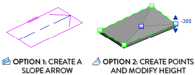
3- CREATE SIMPLE SLOPES WITH FLOORS
It is possible to create slopes using floors. The first technique is to use arrows, where you set a slope angle to an arrow. The second option is to manually adjust the height of the points like is often done with flat roofs.
This way, you can create hardscape like a slightly sloped driveway.

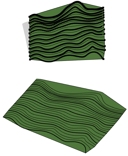
4- Use Toposurface For Complicated Sloped Sites
There are limits to what floors can do. For sites like the image below, use the Toposurface tool.

When modelling toposurface, you should probably create a linked Revit model. When creating topography points, the absolute elevation refers to the height distance to the Internal Origin of the Revit model. That means you should use the Internal Origin height as sea level = 0 if you are modelling from surveyor information.

5- Adjusting Topography Increments and Visual Settings
There is a hidden menu most people have no idea about. Go to the Massing & Site tab and click on the arrow, like in the image below. The menu below will pop.


In the image below, you can see we have primary contours set at intervals of 2000mm. Then, we've set additional secondary contours at increments of 1000mm. The secondary contours are displayed with a thin line style, while the primary ones are thick.

You might notice that the secondary contours are set to start only at 0. If you are using negative values, you'll have to set a negative value here as well. If the sea level = 0, you shouldn't have that problem.
6- Creating Topo From Linked CAD Files
Link a CAD file with topography lines. When creating a toposurface, use the "Create from Import" tool. Select the CAD file, then pick which layer you want to use.


You can see the result below. Make sure that in the CAD file, each topo line has a height z-value. Else, you'll have to manually assign the height to each automatically generated point.
Enjoying this guide? Get this post and many additional tips with our free seasonal pamphlet PDF about landscape! Download and enjoy.

7- Use The "Graded Region" Tool to Modify the Toposurface in Phases
The Graded Region will set the main toposurface to be demolished in the current phase and create a new toposurface.
Click on Graded Region in the Massing & Site tab. Next, select your toposurface and modify the height of topo points to reflect the change during the construction.
As you can see in the view below, we can see both the existing and new toposurface together. The existing one appears in red because it is demolished.

8- Use Railings to Model Curbs
Railings can be used for anything, including curbs. Create a new rail profile family that is shaped like a curb:

Create a railing type that doesn't contain any balusters, Top Rail or handrails, but only a rail with the curb profile. Adjust the height if you want the top of the curb to go beyond the floor or toposurface.

You can host these curbs railings to toposurface or floors:

If you want clean joins between curbs intersection, make sure to activate the Weld option for the Rail Connections parameter in the railing type properties.

9- Creating Sloped Curved Walls
Creating a sloped straight wall is simple. You can use the Edit Profile tool.
However, it is impossible to modify the profile of a curved wall.
There are a few workarounds: the first is to create a sloped reference plane and to Attach the top of the curved wall to it.

The other possibility is to use the Model In-Place tool to model a Void Swept Blend. The Model In-Place feature isn't usually recommended, but it is a legitimate use in this case. In the modify tab, use the Cut tool on the sloped wall. Group the wall & void.

About the Environment Plugin for Revit
The next few tips will be using the Environment plugin for Revit. To be clear, this isn't a sponsored post and Revit Pure doesn't get any reference commission. This plugin is fantastic and will save you insane amounts of time when modelling landscape. It is created by a firm called Arch-Intelligence.
Click here to download the plugin and get a free trial. The cost for an individual license is $350 per year.
Our friends over at team Parallax are also developing a landscape plugin but it isn't yet available.
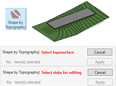
10- SHAPE FLOOR TO MATCH TOPOGRAPHY
This tool allows you to shape a flat floor based on the shape of a toposurface. Select the tool, select the toposurface, then select the floor.
You'll see the menu below appear. You can set the relative elevation to the toposurface, which you should adjust. Click OK and let the plugin calculate.
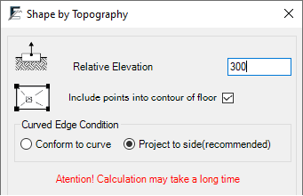
Check out the result below.

Maybe you don't like all the triangulations lines, you can turn them off in the Visibility/Graphics menu.
This way, it looks better:

11- ADD TOPO MODEL LINES CONTOUR TO FLOORS
If you create a floor like in the previous tip, you won't have any contour lines. Good news: The environment plugin contains a tool called Floor Contours.
Select the floor and click on the tool. You'll be asked to set the increment and the type of model lines to be used.

Using the dropdown menu from the same tool makes it possible to update the contour lines or delete them.
12- Set Elevation to Model Lines
Previously, you've learned how to create a topography from an imported CAD file. With the Environment plugin, it is possible to do so within Revit. First, draw a bunch of model lines. Splines are best for this, but you can use any shape.

Next to the Set Elevation tool, you can set an increment, a reference level and a start elevation. When adjusting the values, make sure to press enter. Else, it won't work. Next, click on the small arrow at the bottom right corner to adjust line override and topo tag.

Click on the Set Elevation button, and click on the line one by one, starting with the lowest line. The line acquires the color override you've set, and a text displaying the line height might appear, depending on the options you've selected. This can be done in any view, although it's easier inside a 3D view.

13- Create Surface From Model Lines
Once your model lines are created, and their height has been set, you can use the Create Surface tool.

When using this tool, select the model lines you want to use. The plugin automatically generates a toposurface out of it. No need to use CAD files anymore.

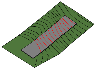
14- CREATE 2D PATTERN FROM FLOOR OR TOPOSURFACE
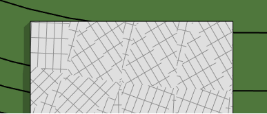
A common issue when using sloped floors is that the model patterns are entirely messed up. Point in case:
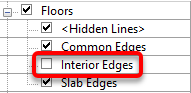
First, go to the Visibility/Graphics of the floor plan view you want to use. Hide the pattern.

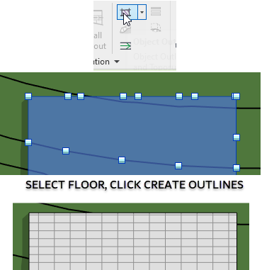
Then, select the floor and click on Create Outlines. A filled region matching the material is automatically created on that view.
We usually advise against using 2D components like lines and regions because they aren't linked to the model. In this case, the team behind the Environment plugin went out of their way to create smart 2D components. First, the name of the region is the same as the name of the floor.

If you modify the shape of the floor, you will receive this pop up:

If you click yes, the filled region will update to match the new floor shape.
Finally, if you modify the floor material pattern, the change will also be reflected in the filled region.
Enjoyed this post? We've got many more tips for you! Download the latest Revit Pure pamphlet about landscape. It's all free.

Source: https://revitpure.com/blog/14-tips-to-master-topography-and-landscape-in-revit
0 Response to "How to Build Topography From Autocad Drawing in Revit"
Post a Comment